the concept in Direction Pattern In Creo Parametric is you have to give a reference side of your part and than you have to give the distance that should be placed between the two features of pattern.
Table of Content
- Step-1 Create Base Plate
- Step-2 Create Feature to be pattern
- Step-3 Select Pattern Type
- Direction Pattern Types
Step-1 Create Base Plate
To perform this tutorial , first make a rectangle with dimension 200-units length , 100-units width. you may choose your own dimensions.
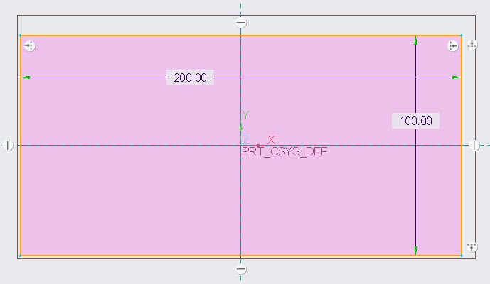
Now use extrude tool to create a solid plate from above sketch. I have selected 30-units as the depth of extrude.

Step-2 Create Feature to be pattern
after making solid rectangle make a hole using Hole Tool or you can use extrude tool for this too. To make hole using extrude tool click at the front face of the plate and then click at extrude icon as shown in the following figure. Creo will take you in sketching window.

In sketching window create a circle of diameter 10-units and at the distance of 20-units from each side of the plate as shown in the following figure.

After creating the circle, as specified in above figure, click at ok button. Now creo will take you in extrude feature window. Here, provide the depth of the hole as 10-units and select the option of remove material as shown in the following figure.

Step-3 Select Pattern Type
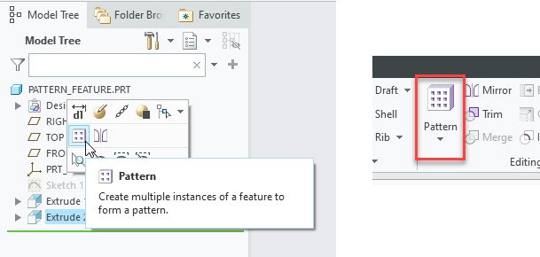
After making hole in plate, select the newly create hole from model tree (which Extrude 2 in my case). when you do this, pattern tool will become active for this feature. Which you can select either from popup-box or from ribbon as shown in the following figure. now click at pattern tool.
After clicking pattern tool, a new window will appear and in which you will need to provide the different option related to pattern. Here select “Direction” as the pattern type.
Direction pattern Options
Let’s discus the available option in Direction pattern in creo parametric briefly. In the following figure
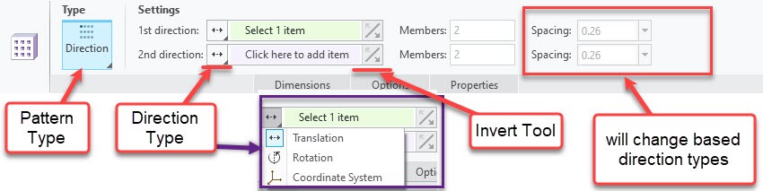
- 1st Direction: As obvious from its name, it is the option to specify the 1st direction of pattern. Direction will be indicated by “Red Arrow” on the model.
- 2nd Direction Members: it has same function as 1st Direction but in different direction based on your selection. direction will be indicated by “Blue Arrow” on the model.
- Direction Type: it is the option to specify the type of direction entity selection. You can see in above figure, three types are listed.
- Translation: it will select straight edge and pattern will be generated along the direction of select edge.
- Rotation: it will allow you to select an edge, but pattern will be generated “around” the edge. Just like it is revolving.
- Coordinate system: it will ask you to select a “coordinate system” and pattern will be generated based on x,y and z coordinates.
- Invert Tool: it will reverse the direction of pattern.
- Spacing: in case of Translation-type, it will specify the distance between the members. In case of Rotation-type it will specify the angle. In case of “Coordinate-system-type”, it will specify the spacing in terms of x,y and z coordinates. You can specify the negative value (-ve) if you want to change the diction as well.
Direction Pattern Types
we have discussed three types of direction pattern in creo parametric. which are Translations, Rotation and Coordinate system. Let’s discus “Direction-types one by one.
Translation direction pattern
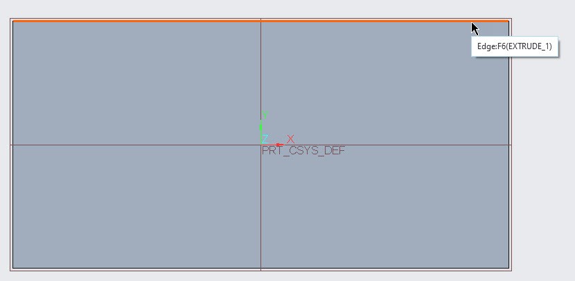
First you need to think, in which direction your pattern should be generated and then select an edge which is in the direction of your choice. In my case I am trying to pattern along the edges as shown in the following figure. I also have labeled them to specify the 1st and 2nd directions as well.

After deciding the direct now select the horizontal edge of the rectangle as 1st direction. After selecting the edge, a “red arrow” will appear in the direction of edge.
Now activate the 2nd direction from the ribbon by click on the message “click here to add item” just beside the 2nd direction option. After that, select the second edge of the rectangle to specify the 2nd direction. A “blue arrow” will appear.

You can set the spacing as showing in the following figure. After completing this you can press the “ok” button.

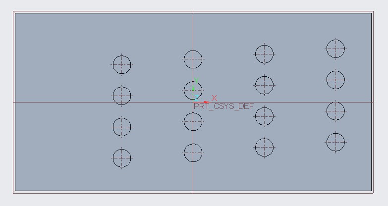
Your final part will look the following figure.

Rotation Direction pattern
You need to perform all the steps, required for the translational direction pattern in creo parametric. But instead of translation select rotation type direction pattern and then select the edge, colored green, as shown in following figure. After this specify the angle and press the ok button to complete the pattern.

Coordinate system Direction pattern
You need to perform all the steps, required for the translational direction pattern in creo parametric. But instead of translation-type select Coordination-system-type direction pattern. After this select coordinate system of the model. After the selection of coordinate system, “input boxes for x,y and z coordinate will appear in the spacing section as shown in the following figure.

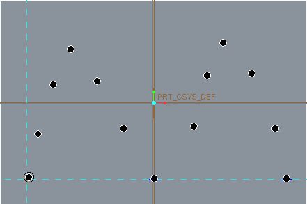
You can set the values of the coordinates as shown in above figure. But as the hole was on the top-right corner of the rectangle. So we need to provide negative (-ve) values for x and y coordinates. In the following figure you can see the negative (-ve) values for x and y coordinates. Also do note the placement of “red arrow” at the coordinate system.
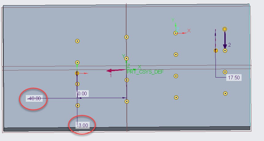
After setting up, press ok to complete the pattern.
Share it
Leave a Reply