Open your CAD software Creo. Click at file > new> name the file> press ok
Select the front plane and click at sketching button to enter into sketching window.
Draw a circle with diameter 5 units and center at the origin as shown in fig below and press ok
Extrude this circle up to the length 5 units make sure to use extrude center symmetric form means same length on the both side of the reference plane.

Now select any circular face of the solid part and click at sketching button.

Again draw a circle concentric to previous circle and make its diameter 6.5 units and press ok .
In main window extrude the last bigger circle up to 0.5 units towards outward, as shown in fig, and press ok . Now I will call this new extrude as plate.
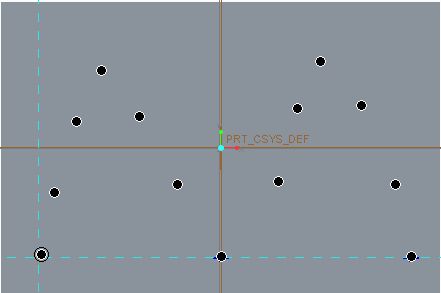
Select the upper surface of plate and click again at sketching icon. Now we have to draw a small circle of diameter 0.3 units and at a distance of 2.90 units from the center, as shown in following fig, and pres ok. I changed the view to “Hidden line” for better understanding just in the sketching window.
Now we will use extrude cut to make a hole using extrude to selected surface option or any other option you want to apply and press ok .
This hole will be used to place the bolt for joining with other cylinder. So we need to make a pattern of this hole. Select the hole click at pattern and use Axis option to create 5 holes at equally distance from each other as shown in fig below.
Now we will use a little power of this CAD software. That is we will mirror the selected part of above model.
For this click at pattern in model tree then press and hold the ctrl key and click at extrude of the plate. After selecting the both plate and the pattern of holes, click at mirror button shown in main window.


This will ask you to select the reference plane for mirroring. For this purpose select the front plane and press ok. This will generate the plate with holes on to the other face of solid cylinder that we have extruded first.
To make the hole at the center of the part select the plate surface and click sketching icon then make a circle of diameter 4 units and press ok to return to main window.
Now again use extrude cut with selected surface option and make hole from surface of one plate to the surface of other plate ( through hole). This will complete our cad model of displacer cylinder.
In final our Cad model will be look like as shown in fig below.
Share it
Leave a Reply