Axis Pattern in Creo Parametric is simplest pattern type. it makes pattern about an axis of the given part or selected axis of the part. it’s name is itself well explanatory. let’s start it’s exercise.
Table of Content
- Step-1 Create Base Part
- Step-2 Create feature to be Pattern
- Step-3 Select Pattern Type
- Step-4 Axis Pattern Parameters
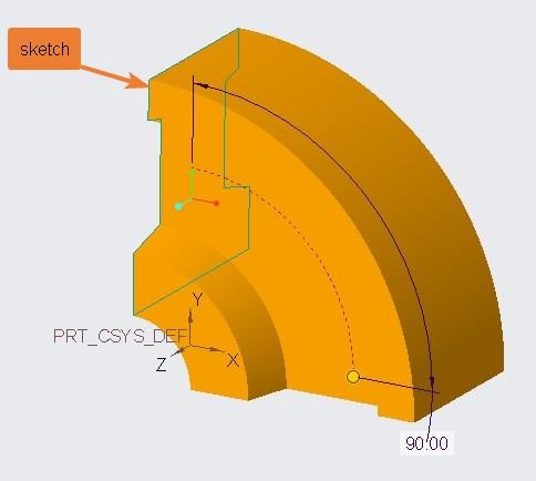
Step-1 Create Base Part
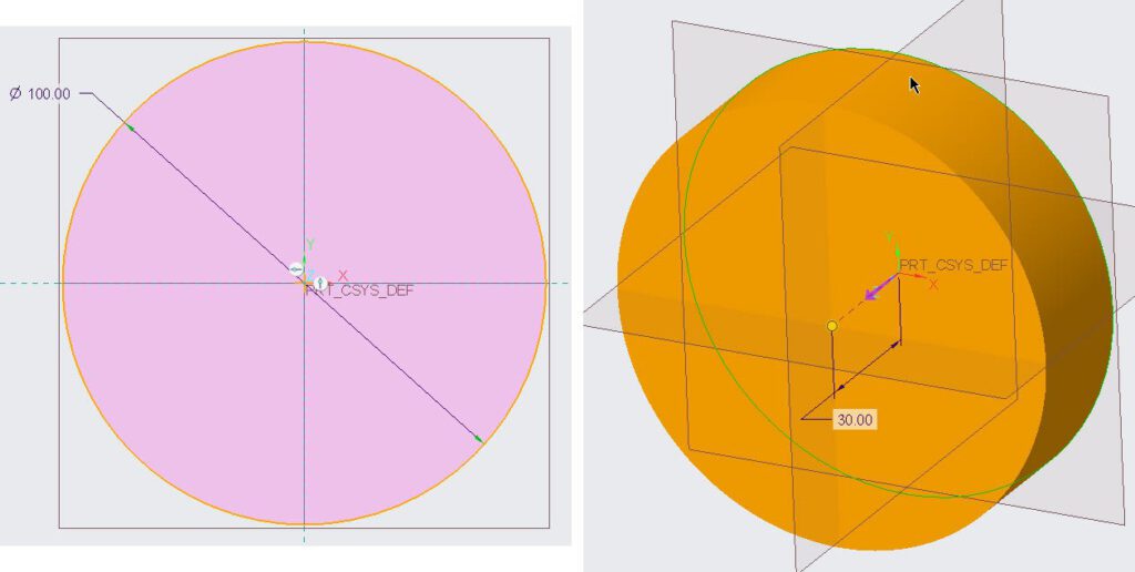
first, make a solid disk in Creo Parametric using either extrude tool or Revolve tool. Initially, for this CAD tutorial, you can take its diameter 100 units and depth of the disk is 30 units. These dimensions are arbitrary and you can assume your own dimensions.
Step-2 Create feature to be Pattern
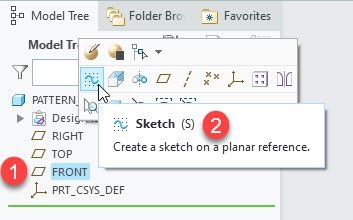
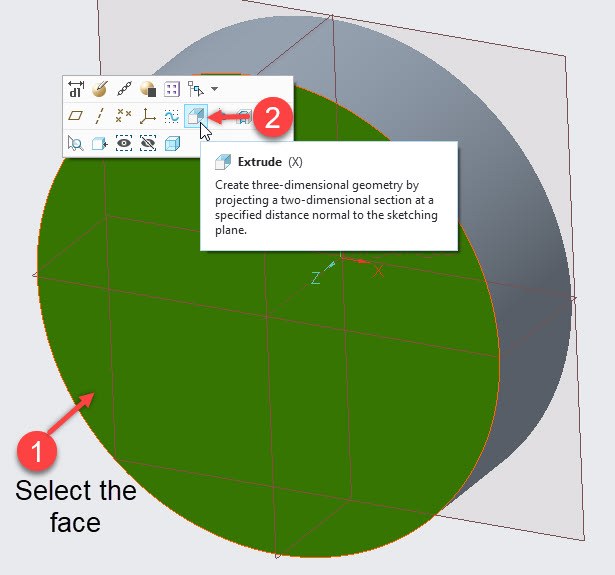
after making disk use either hole tool or extrude tool to make a hole in this disk. To create hole using extrude feature, first, select the front face of the disk and click at extrude button as shown in the following figure. Sketching mode will become active.
In Sketching window, create a circle at 20-units distance from the origin. Also assign 5-units value to its diameter.
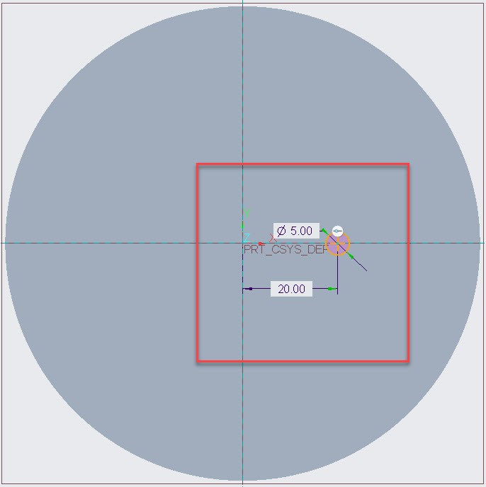
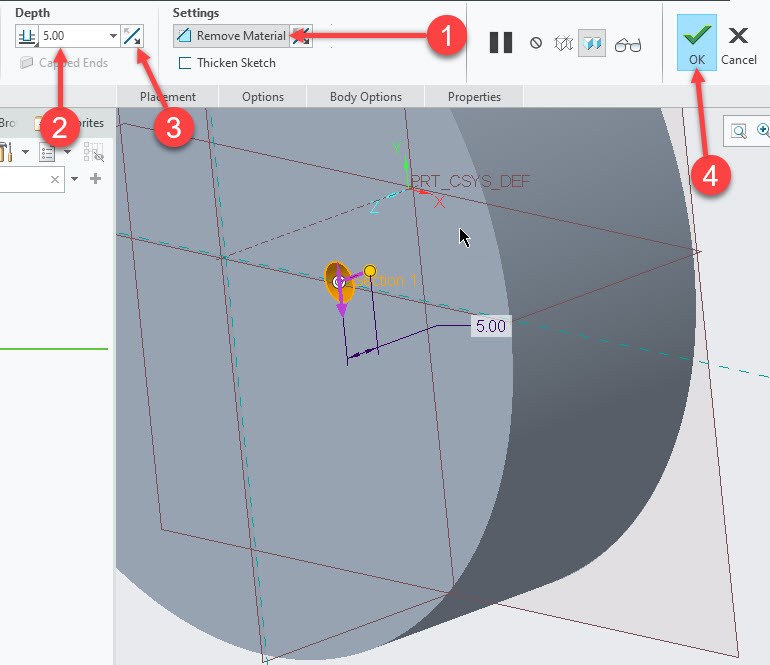
I used extrude tool, with its remove material option to create a hole. The depth of hole was set to 5-units. You can assign your own value to depth.
Step-3 Select Pattern Type
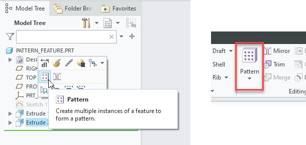
After making hole in disk, select the newly create hole from model tree (which Extrude 2 in my case). when you do this, pattern tool will become active for this feature. Which you can select either from popup-box or from ribbon as shown in the following figure. now click at pattern tool.
After clicking pattern tool, a new window will appear and in which you will need to provide the different option related to pattern. Here select “Axis” as the pattern type.
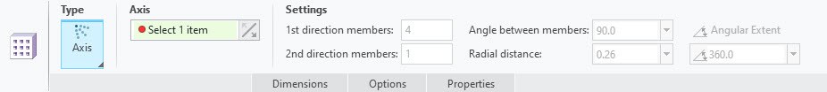
As you can see in above picture that we haven’t selected any axis yet, so Creo parametric is asking us to select an axis by highlighting “Axis” option box. Now select the axis of the disk.
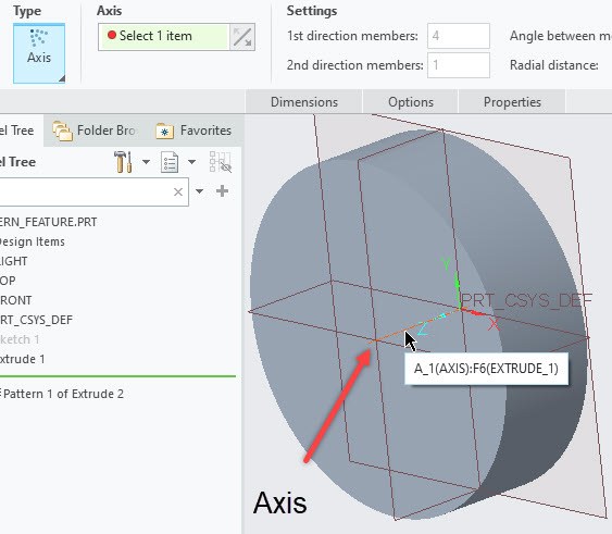
Axis pattern Options
As soon as you will select the axis, Other options for Axis-Pattern will become active or editable. Here I will explain briefly about the options available in axis pattern in creo parametric.
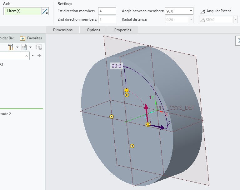
In reference to above picture following are the different options in Axis pattern:
- 1st Direction Members: direction is indicated by “Red Arrow”. Which means, it is the option to specify the number of pattern members in circumferential direction. 4-members means 4 number pattern members.
- 2nd Direction Members: direction is indicated by “Blue Arrow”. Which means, it is the option to specify the number of patterns in radial direction. 2-members mean two set of pattern members and each member will have number of pattern items according to 1st Direction.
- Angle Between the members: set the angle between two members. It is applicable to 1st direction members only.
- Angular Extent: it is by default “inactive” and can be toggle on by click on it. This option will distribute the members evenly in circumferential direction. “Angle Between the members” option will become inactive as angle is now calculated by dividing the angle option (just below the Angle extent) by the number of members in 1st direction.
- Radial Distance: it will specify the distance between the members of 2nd Direction. You can specify the negative value (-ve) if you want to change the diction as well.
Step-4 Axis Pattern Parameters

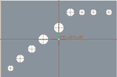
Now the set the options as shown in the above figure. If you want to exclude some of pattern members from creation, then you can click at back-dot inscribed in yellow circle. Yellow circle will change to small white circle indicating that the specific item has deactivated and will not be generated.
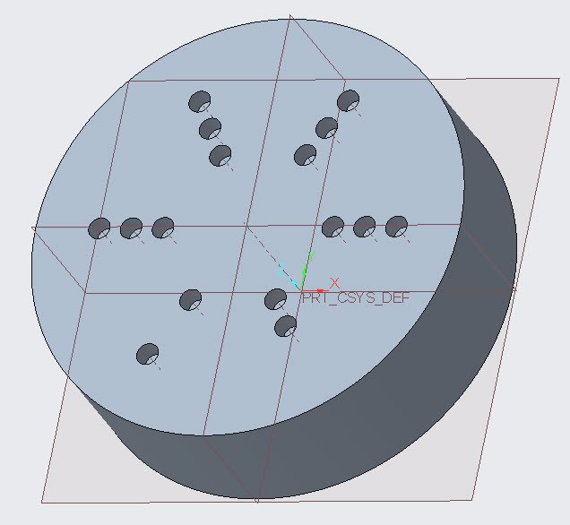
The final part of Axis-pattern tutorial is shown in the following figure.
Share it
Leave a Reply