Introduction
A Revolve feature is based on a two-dimensional sketch. It rotates a sketch about an axis or an edge to add or remove material. You can either select the sketch first then start the Revolve tool, or you can start the Revolve tool and then select the sketch.
We need two things to utilize revolve tool.
- An axis or an edge (about which our sketch will rotate)
- A sketch (at one side of axis) which must not intersect with the axis.
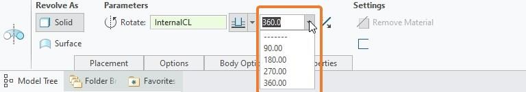
Before starting our exercise let’s have quick view to the options available in revolve tool. We can see that, options available in revolve tool are similar to extrude feature but with one difference. Which is, we can provide angle up to 360 degrees (positive/negative). I already have explained these options in Extrude feature tutorial, so I am not going to explain them here.
You can either select the sketch first then start the Extrude tool, or you can start the Extrude tool and then select the sketch.
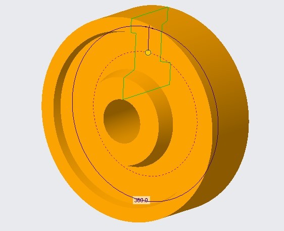
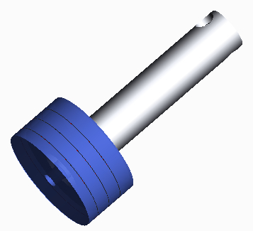
So, let’s start the tutorial for revolve tool. In this tutorial we will create the following model.
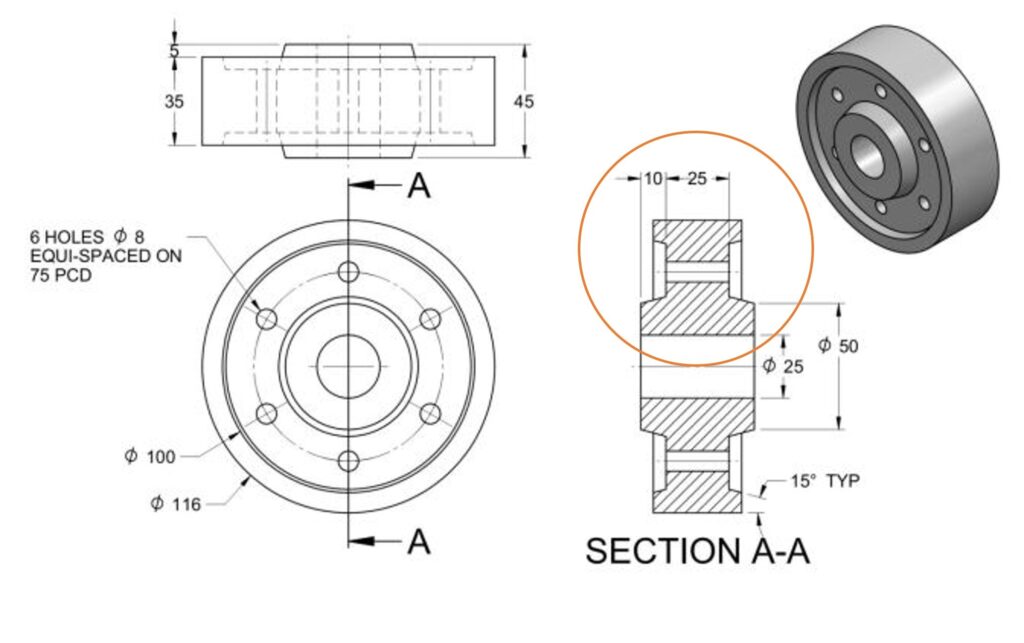
In above picture, from section view “section A-A”, we can observe that cross-section of model (we can say wheel for now), at any side of the central axis, remain same throughout the rotation. So, we will create one half of the sketch from “section A-A” for our sketch. As some diameters are given in the figure and we need to create only half of the sketch so, we will use radius instead of diameter while dimensioning our sketch.
We will perform this exercise either by
- creating sketch first and then select the revolve tool
- or you select the revolve tool first and then create a sketch.
Let’s create a wheel with the given dimension, as shown in above figure.
Step-1 opening Creo Parametric
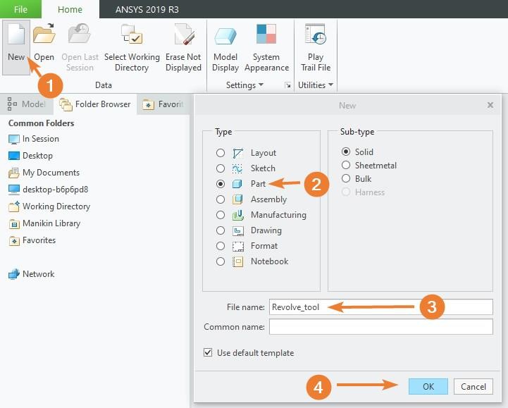
So, start Creo parametric and follow the steps mentioned below and shown in Figure ?1?1.
- go for new part file. A dialog box will open
- now select the “part” option in “type” section and
- change the name of the file if you want to. After this
- just press “ok” button which is located at the bottom of the dialog box. After this working space will appear where you can create your model.
Step-2: Create A sketch for revolve tool
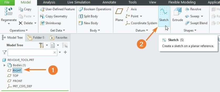
Now select the “Right Datum Plane” from model tree and then click at sketch button as shown in following figure.
After clicking at sketch button, “sketching window” will appear where you can draw the following diagram using line tool.
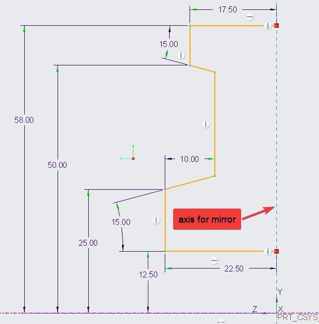
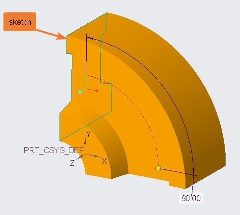
As you can see in above picture I have created half of the sketch, as I am going to mirror it about “axis of mirror”. Using mirror command in sketch I have created the following complete sketch.
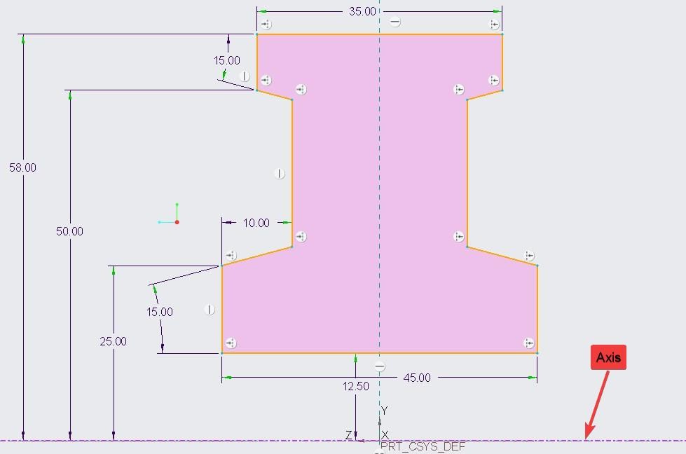
Please note that, I have created a horizontal center line as an “axis”. This will act as axis of revolution in revolve tool.
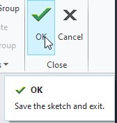
At this point we have created a required sketch as well as an “axis” within sketch to fulfill the revolve tool requirement. So now we can press “OK” button in sketching windows to return to previous model window.
Step-3: Using Revolve tool
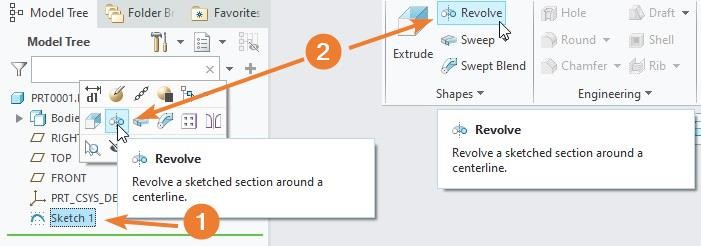
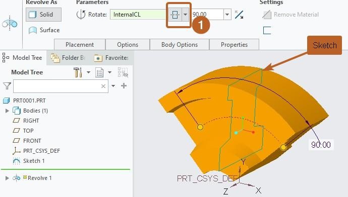
Now select, your newly created sketch, in the model tree and then click at revolve tool button. If you are using version 7.0 or 8.0 then you can use any of the method shown in the following figure.
After selecting It will show you 3-D model. in the following figure I have selected the value of angle as 360 so I can create full required model. For now I am not going to create holes in it but you can create them either by using hole command or by using extrude feature.
Revolve on one side
Now we will explore the options, available in dashboard, a little to understand them. So it become easier for you to utilize them as you need. If we change the angle value from 360 to any other value, say 90, then by default Creo parametric will revolve only one side of the sketch as shown in the following figure.
Symmetric Revolve
Now change the the direction of material addition to symmetric. After which you will see that creo parametric is revolving the sketch on both side equally (as defined by symmetric constraints).
Revolve on both side of Sketch
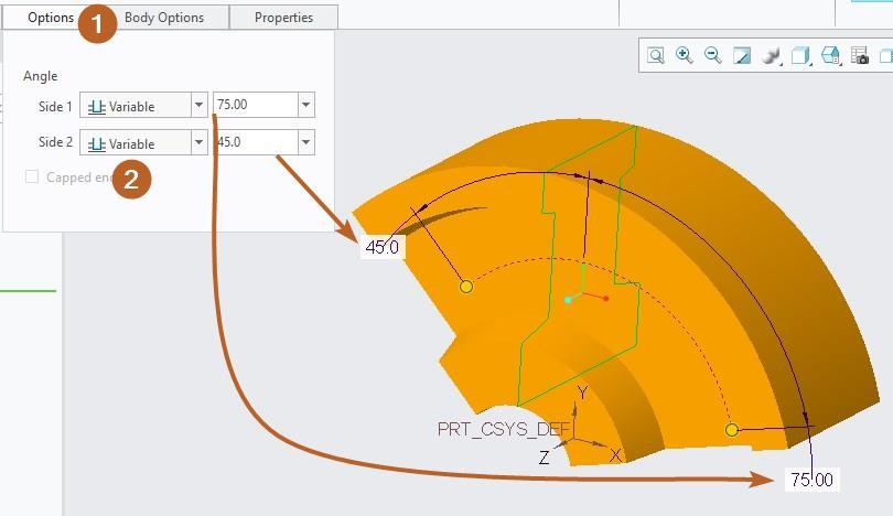
If you have condtion(s) such that you need to revolve the sketch differently on both side. To achieve this, click on the “Option” tab and then enable the “Side 2”. For now, set angle type as “variable” for both side and provide your desired value against each side. In the following figure I have provide 75 and 45 value to side-1 and side-2 respectively. If you already have some surface then you can revolve it up to that surface.
Share it
Leave a Reply