Table of Contents
Introduction
Sweep feature in Creo Parametric will simply add the material along the provided path. This path is called Trajectory (I simply say it sweep profile) while the cross section which you will sweep along this path Is called sweep section. In extrude feature we add or remove material along the Normal of the sketch and in Revolve feature we either add or remove material about some rotational axis. But there are some cases in which use of either revolve tool or extrude tool is not easy. In these cases, we can use sweep feature to create require part.
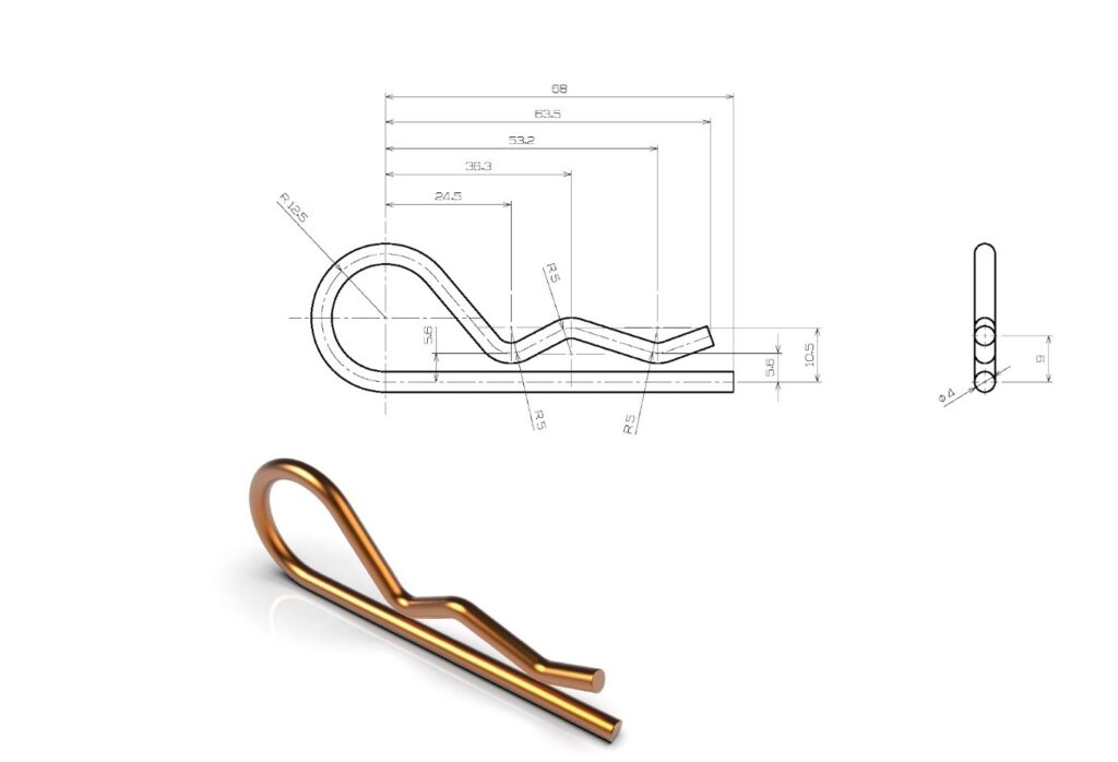
Both constant cross section and variable cross section sweep can be created. But in this tutorial, we will explore sweep feature for constant cross section only. In this tutorial we will try to model the following part. so let us go through some steps of creating sweep feature in Creo parametric.
Steps For creating Sweep
Step-1 create a Trajectory (sweep profile)
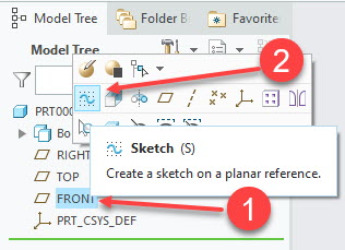
In sweep feature, we have to create trajectory first and then we will be able to use sweep feature. So, in first step we will create a trajectory. To do so I am assuming that you are already in part module. So now select front plane and click at sketch icon.
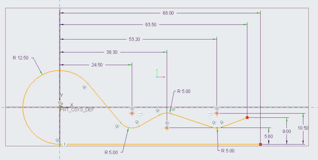
After clicking on sketching icon creo parametric will take you into sketching mode where we will create the following sketch. I have created this sketch using line tool, arc tool and with the help of some points.
Step-2 selecting sweep tool and specifying section location
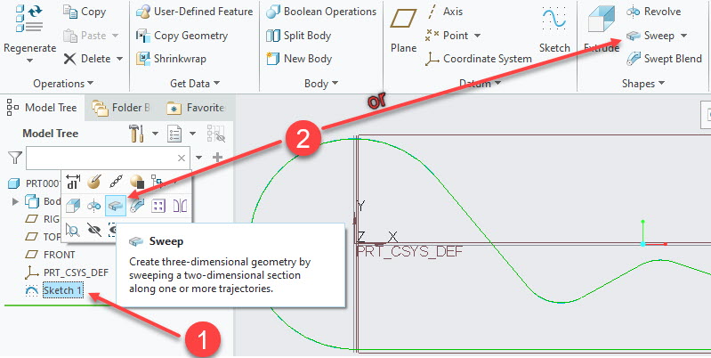
After creating sketch, click at ok button to exit the sketching mode. Now select the newly created sketch from the model tree and click at sweep tool icon. In newer version of Creo parametric, a pop box will open as soon as you click at the sketch. So you can either select sweep feature within that pop-up box or can select it from the ribbon as shown in the following figure.
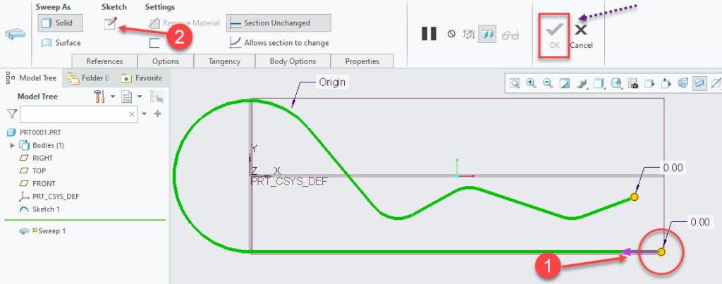
After clicking at sweep tool icon, configuration options for sweep will appear in the ribbon. In the following figure you can see a “purple” arrow which is highlighted as step-1. Creo Parametric will create sweep section at the Location of this arrow or this will be the start of sweep creation. So, in current case, it has to be at the location specified in the following figure. If in your case this arrow shows up at the other end of trajectory, then you can change its location by simply clicking ON it.
Step-3 creating sweep section
After specifying location of arrow now click at the sweep section tool as shown in step-2 in the following figure.
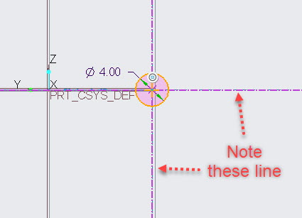
After clicking sweep section tool, creo parametric will take us into sketching mode again. But this time we need to create our required sweep section. Which is a circle in current case. So we will create a circle at the intersection of lines which I have pointed out in the following figure.
after creating a circle, just click at the OK button and creo parametric will take you back into the previous window which is window for sweep tool and you will see addition of material along the trajectory.
Now you can click ok button to complete the sweep feature.
Creating 3-D sweep in Creo
As we know that there are two requirements for the sweep feature.
- We need a trajectory either close or open
- We need a sweep section. Which will follow the trajectory.
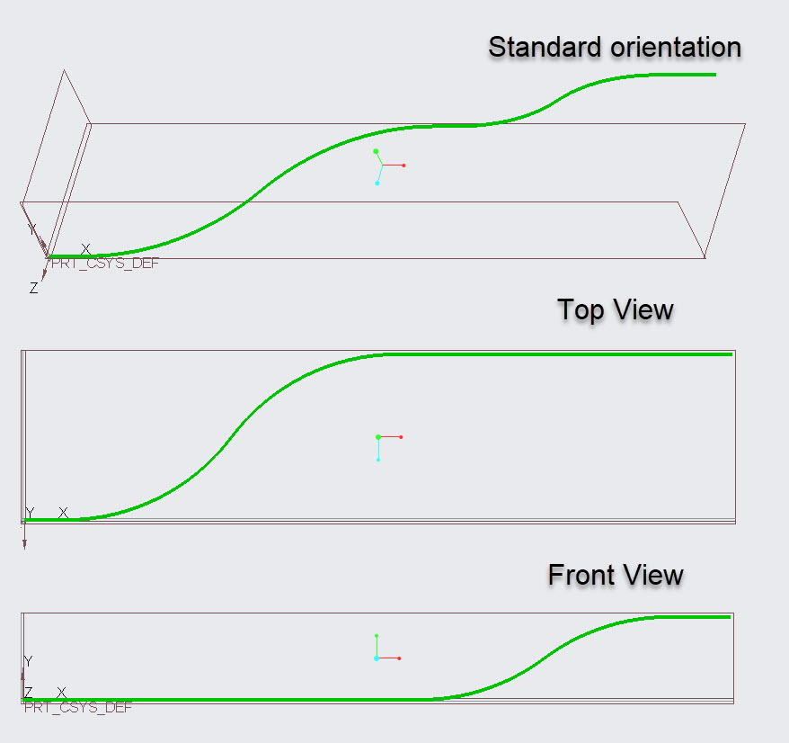
So if you want to create sweep feature in 3D then you are required to create trajectory in space (in 3D). in the example, that we have discussed in this tutorial, we have drew 2D sketch. But we can create a curve or sketch in space by using intersection Tool, which is one the method for creating 3-D curve. in tutorial, Understand the intersect tool, we already have created a 3D Curve. So here we will create its cross section as well.
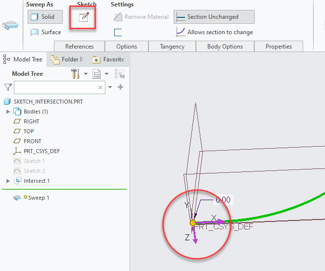
Now resume the intersection tool exercise (if you haven’t created the sketch then follow the tutorial to create 3D curve first). I Placed the arrows at the origin to imagine the orientation of cross-section with ease. we can change, later, the orientation of sweep section by clicking at the arrows.
After placing the arrow at origin, as shown in the following figure, click at the section creation button as highlighted in the following figure. CAD software will take you into the sketching mode.
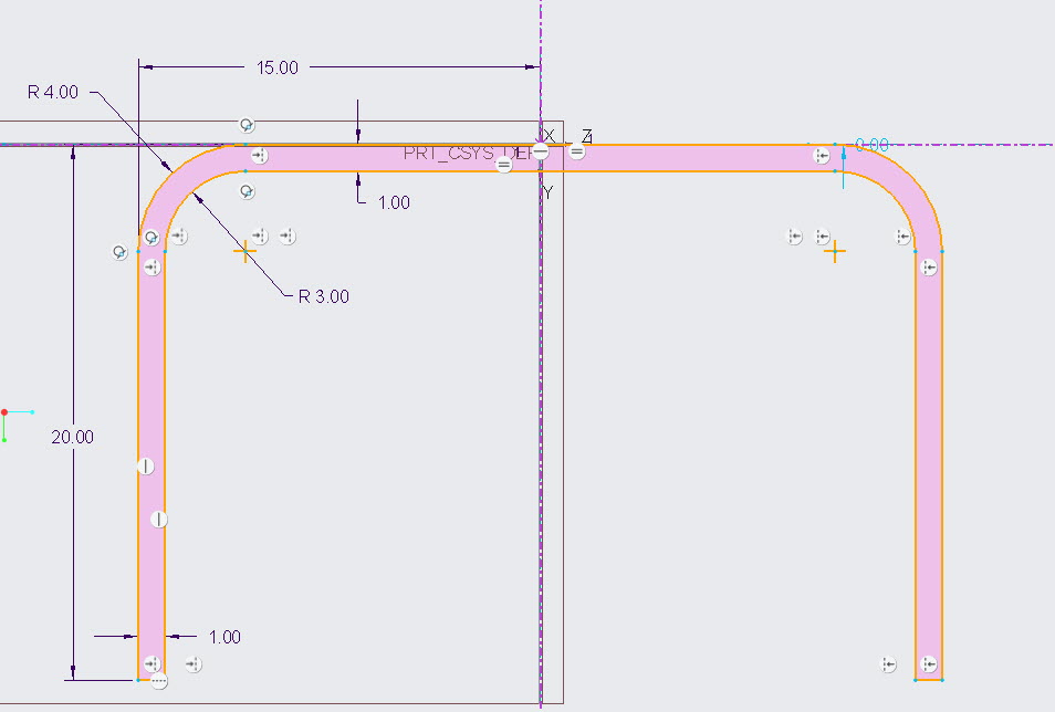
In sketching window we need to create the following sketch. I created this sketch using line tool. round was created using round tool in sketch. Also, I created only half of the sketch and to complete it, I used mirror option in sketch.
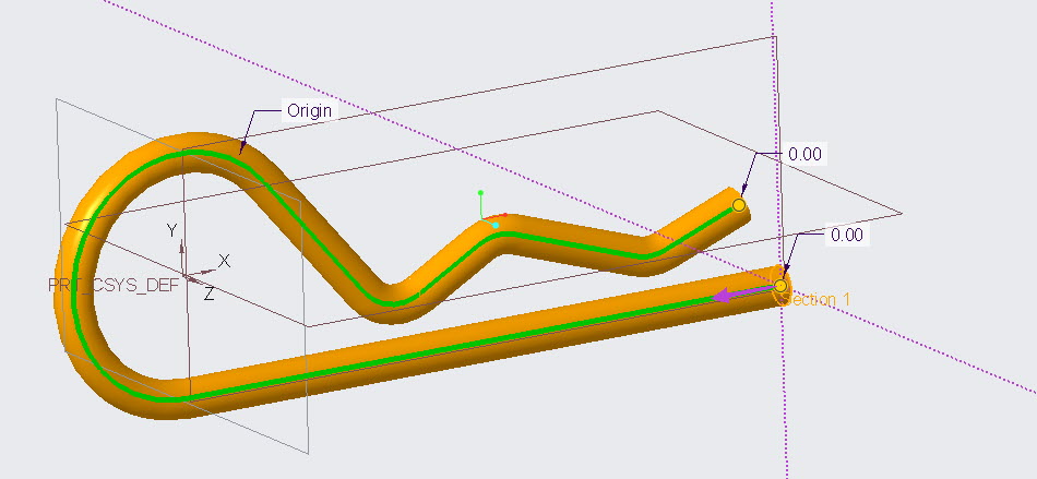
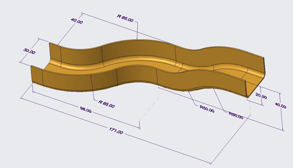
After creating the sketch just press ok button in sketching window to complete the sketch and CAD software will show you the 3D model created using sweep feature as shown in the following figure.
Share it
Leave a Reply