Blend Feature in Creo Parametric is feature in which you can create a part with variable cross sections. these cross-section can be of same type or of different types. in extrude feature and revolve feature you can create part with constant cross section.
Table of Content
Blend Feature Requirements
In Creo parametric there are two things which are required to create part using blend feature.
- Multiple sketches (cross sections) on different planes.
- Each sketch must have same number of sketching entities.
For example, in circle there is only one sketching entity while in square there are four lines, so it contains four entities. To blend in between square and circle, the circle must be divided into four arcs.
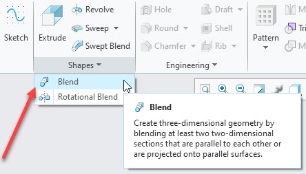
Blend feature options
i am assuming that you have created a new part in Creo Parametric. in main window of part module click at blend feature as shown in the following figure.
after clicking at blend feature icon, the tool will become active and its control/option will appear on the ribbon in Creo Parametric. Here we will discuss these options a little so we can have better understanding of the feature. As you can see in the following figures, the ribbon area is divided into different sections. there are four sections in “parallel blend feature while there are five sections in rotational blend.
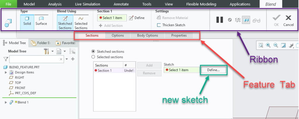
- Type: section will give you option whether you want to build solid or surface model
- Blend Using: section gives you option either you want to create new cross sections for your model or you already have created them before using blend feature.
- Sketched section = you will sketch each cross section
- Selected sections = you already have created the sketches and now you will select them for your use.
- Section 1: The options in this section will change based on your selection in “blend Using” section. It will help either by creating sections or by selecting sections depending on your choice.
- Settings: you can select the option to remove the material. You can also create thick model not solid if you like.
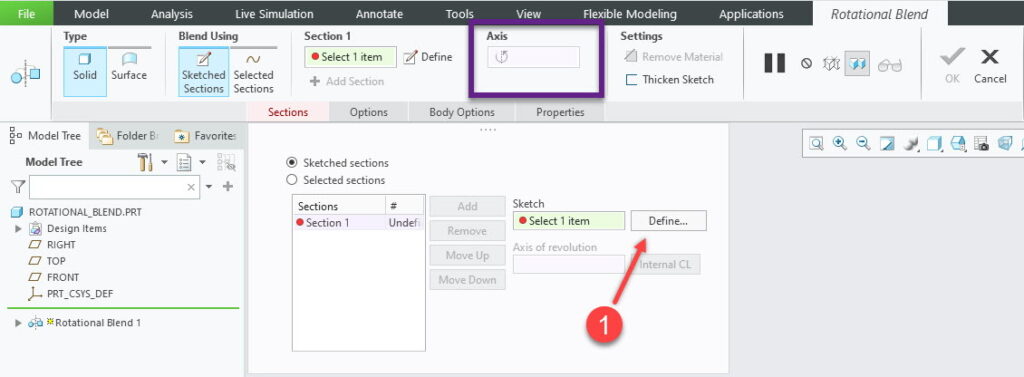
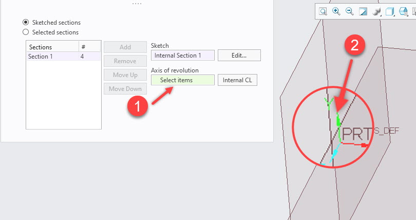
- Axis : this will appear only in rotational blend feature. this option will define the axis of revolution in rotational blend feature.
Blend feature Types
We can create model with variable cross sections by three methods.
- Parallel section Blend feature.
- Rotational blend Feature
- Swept-blend feature
Now we will discuss them one by one.
Blend using parallel Section
In extrude feature we can add/remove material in the direction of normal to sketching plane. The same principle applies here. That is, you can create a part with variable cross section, but addition or removal of material will be in the direction of the Normal (of the sketching plane).
There are two options that we can use to create part in blend feature.
- Selected Sections
- Sketched Sections
if we already have created the sketches /sections then we will use ” selected sections” option. but if don’t have any section/sketch in start then we will use “sketched section” option. for now we will use explore Sketched-Sections first.
Step-1 Creating first Section (Rectangle)
As we haven’t created any sketch yet, that’s why software has highlighted “section” tab just below the ribbon. You can see the button to define a sketch.
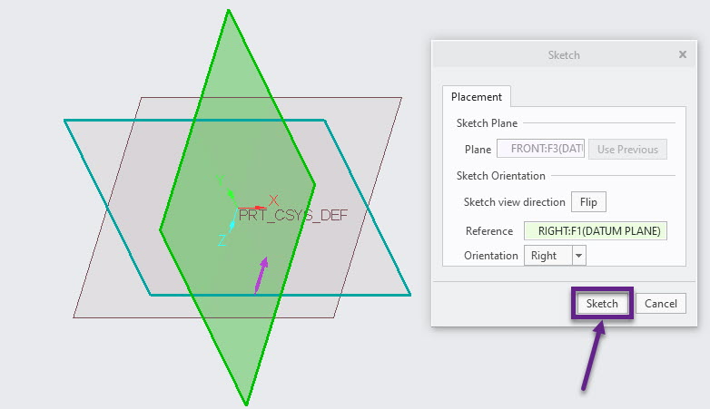
To use blend feature we need to create sketches first and we will do it by clicking at the “define” button as highlighted in above picture. after clicking at define button software will ask you to select a plane. so click at the front plane and then click at “sketch button and Creo will take you into sketching window.
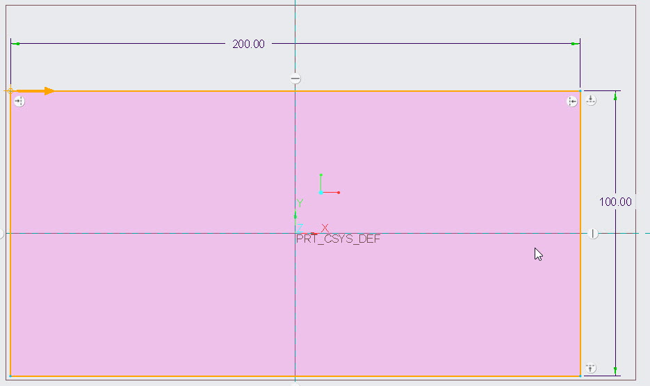
In Sketching window, we will create a rectangle as our first section. Do notice an arrow at the top-left corner of the rectangle. This is the start point of blend and Creo Parametric will join start-points of all the sections using a curve. So, you will get a twisted part if starting points of sections are not aligned.
After creating rectangle click Ok in sketching window.
Step-2 Creating Second Section (A Square)
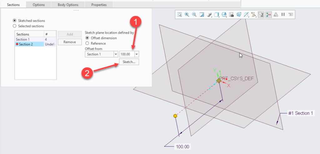
After clicking at ok button in previous step, windows for blend feature will appear again. But this time it will ask you to provide offset distance of section2. I provided 100 units, for now, and click at “sketch” button as shown in the following figure. if “sketch button is not active in your case then first select the “section2” (highlighted in following figure) in sections region then sketch button will become active.
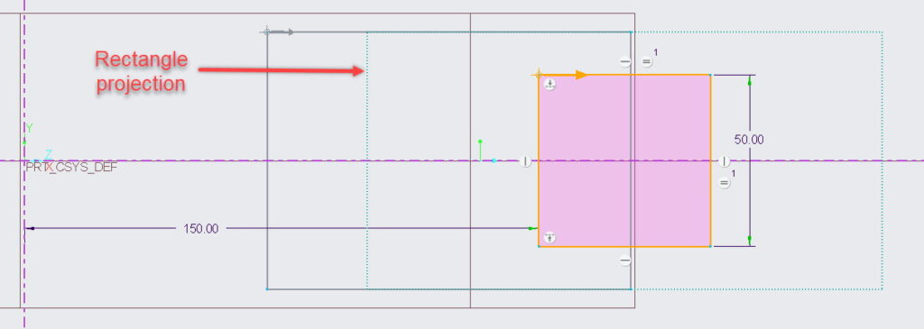
Sketching windows will appear again for second section. So create a square this time as shown in the following figure. You will see previously created rectangle as well for your reference. Do notice the position of arrow on the square.
After creating second sketch click at ok button to complete the sketch.

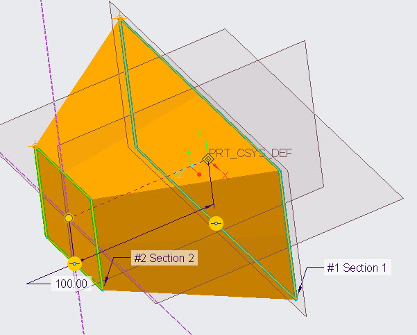
Now you will see a part created using blend feature.
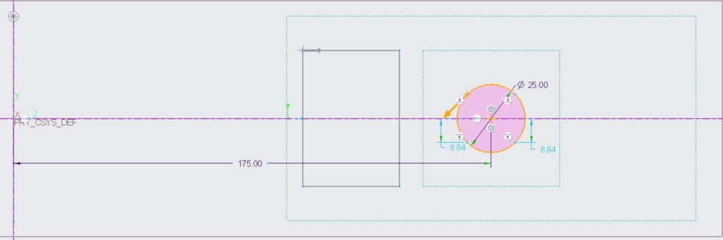
Step-3 Creating third section (Circle)
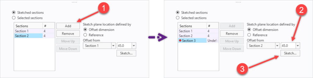
But in this tutorial, we will create third section as well. To do this click at the “Add” button. Step creating third section same as mentioned in previous step (step-2). But this time we will create a circle. Keep offset distance of circle to be 200 units, as shown in the following figure, and click at sketch button.

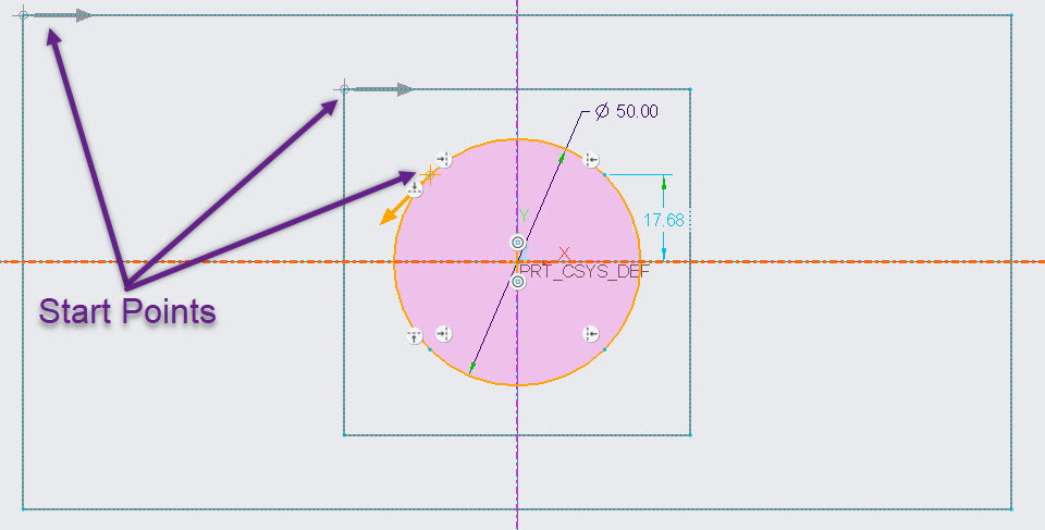
In sketching window, I created a circle and then divided it into four parts. You create this circle by creating four arcs. Do note the position of the arrow and click at ok button in sketching window.
Now Creo parametric will show you the following model. In which you can see we started with a rectangle then changed it into a square and then change it further into a circular cross section.
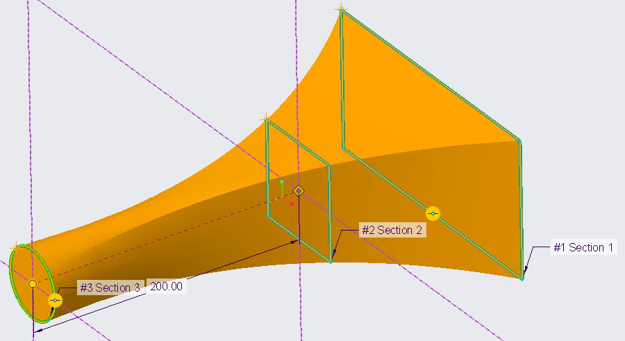
Rotational Blend in Creo Parametric
Rotational blend is like revolve feature but with option to vary the cross sections. Requirements for this blend feature is the same as the requirements of blend feature and revolve feature combined. That is
- At leas two sections are required
- Sections must have same number of entities
- An axis of revolution is also required
- All the section must be on the same side of axis
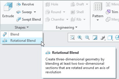
To star with the tutorial, create a new part in Creo parametric and click at the rotational blend icon as shown in the following figure.
Step-1 Rotational Blend First Section ( Rectangle)
Options on ribbon in rotational blend feature is same as discussed in previous section. The only difference is the addition of axis- section in the ribbon.
So click at “define” button and select front plane to create first sketch.
Here we will create rectangle again but this time we will create it at a side of the vertical axis in sketching plane. so you can see in the following figure, the rectangle is around 100 units away from the vertical axis. Click OK in sketch after creating the sketch.
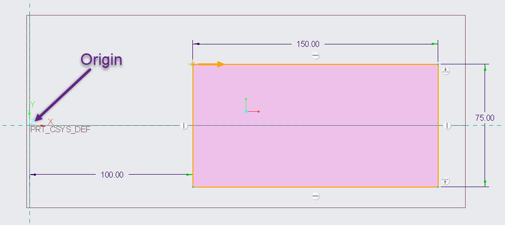
As we haven’t created axis of revolution, so we will select Y-axis as our axis of revolution.
Step-1 Rotational Blend Second Section ( Square)
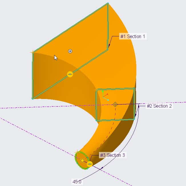
After selecting axis of revolution click at the “Add” button to create second section. This time software will ask you offset angle so you can provide 45 angle for your next section.
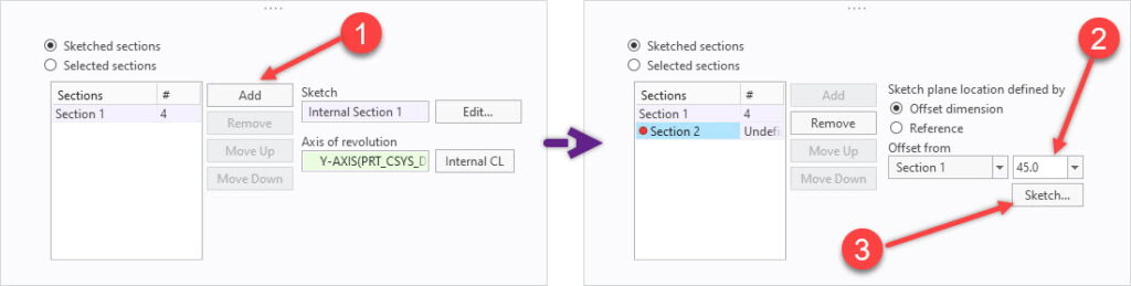
After providing angle click at sketch button and create a square in sketch as shown in the following figure. Do notice the position of start-point. After completing the sketch click at OK button in sketching window.
Although you should see a part created with blend feature.
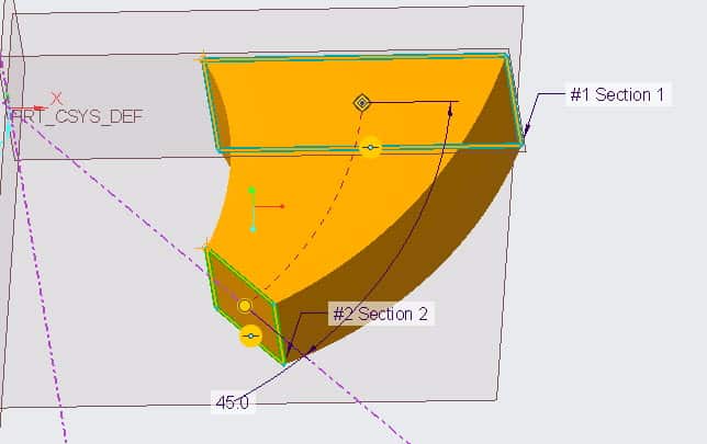
Step-3 Rotational Blend Third Section ( Circle )
but we will create another sketch and this time we will create a circle. After providing 120 as offset angle, click at sketch button.
In sketching windows create a circle as shown in the following figure and click OK in sketching window.
You should see a part revolving about Y-axis and its cross section is changing from a rectangle to square and finally a circle.
Share it

Leave a Reply